But why 10 kΩ?
19/03/2017
Why 10 kΩ? It's the question posed by Giome in his comment on the "additional module". It's undoubtedly a question that everyone asks and no one dares to ask. As usual, it's obvious for those who know and a mystery for the others. If the answer provided here is satisfactory, Giome will have rendered a great service by posing this question.
Schematically, the electronic connection to a GPIO (General Purpose Input Output that is to say general purpose input output port) is the following:
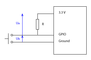
On the left of this diagram we have the symbol of a push button that corresponds to the functioning of the "impulse" sensors. For the sensor used on the water meter of the real-time water consumption visualization system, it's just that. For the counters used for monitoring electricity consumption it's the equivalent in electronic version. In both cases, an impulse corresponds to what would happen if you briefly pressed the push button: a short-circuit between the GPIO input and the ground.
At the level of the GPIO input, we want the translation of this impulse in binary form: a brief passage from 1 to 0, that is to say the passage of the voltage Ub from 3.3 V to 0 V, then a return to 1 (3.3 V).
If we connected only the push button, the value read by the GPIO would be undetermined (we say "floating"). To maintain it at 3.3 V, we connect it to a 3.3 V output. This is what we call a "pull-up" because it pulls the value read by the GPIO upwards.
If we connected the 3.3 V directly to the GPIO, without intermediate resistance, we would have, during an impulse, a short-circuit of the 3.3 V to the ground!
The pull-up resistance therefore serves to protect the 3.3 V output to avoid burning the circuit. The intensity is then limited to Ua/R. With a 10 kΩ resistance the intensity is therefore 0.33 mA, largely below the limit of 16 mA recommended for the limit of the current drawn from one of the GPIO. We could have put less than 10 kΩ but it's a commonly accepted value for a pull-up resistance. It's the one used for the version 1 of the electricity consumption sensor.
Moreover, it is also possible to activate, by a software instruction, an internal pull-up resistance, one per GPIO, of an announced value of 50 kΩ.
If we activate this internal pull-up resistance, we can therefore dispense with adding an external pull-up resistance. It's the choice made for the version 2 of the electricity consumption sensor.
Which effectively simplifies the assembly.